The documentation below is done as the project evolved, and includes experiences and lessons learnt.
Schematic in Altium
RAPC732X (J1) is the power input port (DC 9V barrel jack)
FDC5614P (Q1) is a p-channel MOSFET for the polarity protection.

Fig 1. INPUT and FILTER/POLARITY PROTECTION
RN112APC (J3) is a 1/4'' guitar cable jack.
PTV09A-4020U-B104 (R2) is a A1M potentiometer.
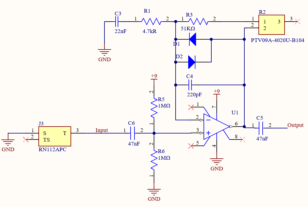
Fig. 2. tubescreamer circuit
The effects part of Fig. 2. is inspired by the design of "hauntologerfx" on Instagram.
ANT11SF1CQE (S1) is a flip/toggle switch.
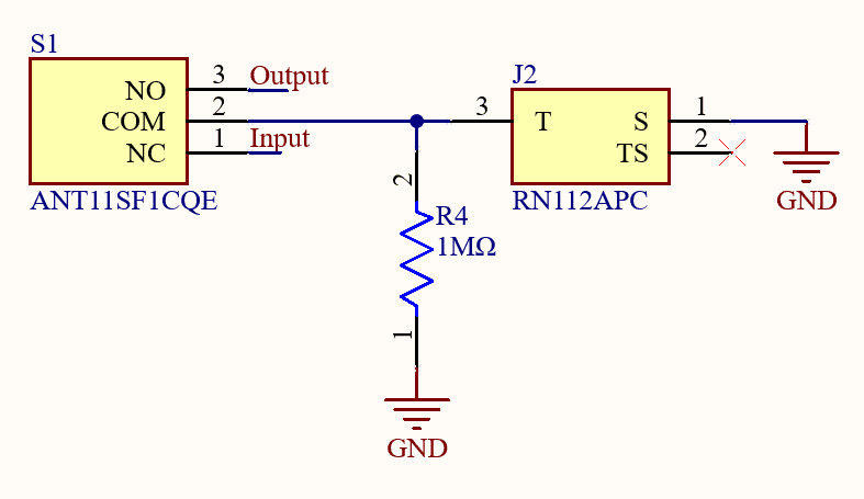
Fig. 3. switch and output circuit
LTspice simulation
I realized that I must include non-idealities in the simulated guitar input, which includes low frequency hums, high frequency noise, and other non-idealities such as guitar pickup resistance, inductance, and capacitance.
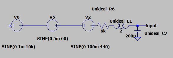
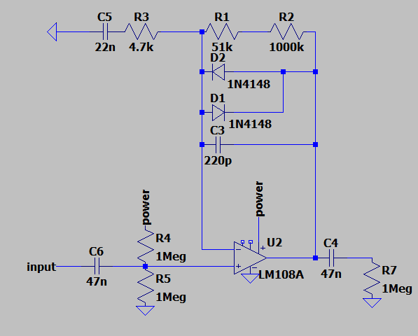
This is the non-ideal guitar pickup waveform and then the output waveform with the tubescreamer effect.
input (blue) and output (green) of the simulated circuit.

PCB Assembly
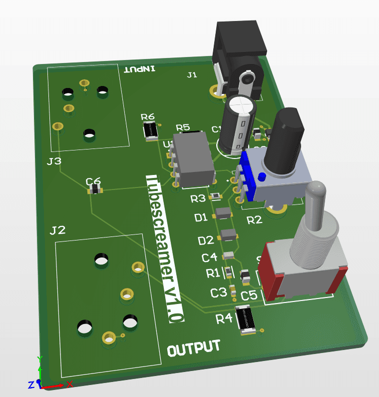
generated model looks promising.
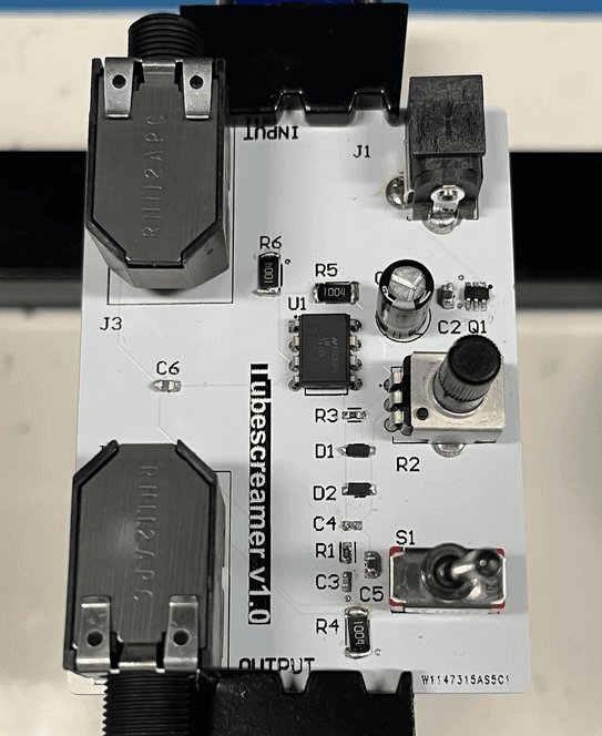
Above is the fully assembled board, all hand soldered.
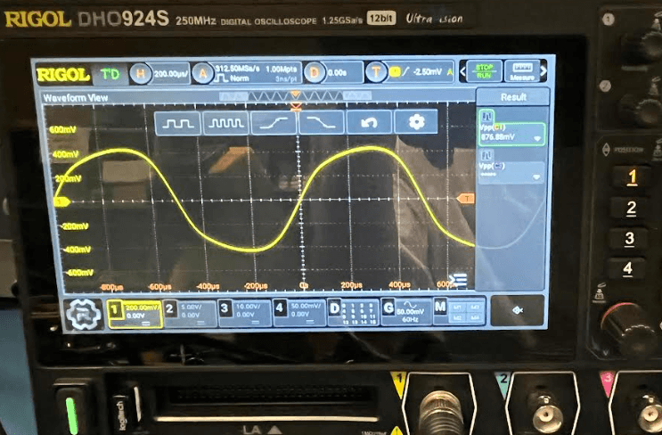
Here is the output waveform from a sinusoidal wave, the output looks almost identical to the Spice simulated model.
Conclusion
Due to the nature of online PCB and components ordering being long and expensive, I was very careful during my design and testing process; this paid off with the final product working perfectly on the first try.

Tubescreamer Guitar Pedal
Tubescreamer Guitar Pedal